The ambient temperature measured by the temperature sensors around the FPGAs can be written to the data stream with the status trigger. This information can be used during the ofline analysis to monitor the change in the temperature since the last TDC calibration.
Most endpoint designs need some configuration bits being programmed after the FPGA has been initialized. Usually these settings depend on the use of the design or specific hardware (e.g. thresholds) and can not be hard coded in the design itself. Now there is the option to store register settings in a separate section of the on-board Flash ROM - all user registers (addresses above 0x8000) can be stored there and can be loaded automatically after a reload of the FPGA design. This can be used e.g. to power cycle an FPGA without requiring interaction from some software and have it back in operation after about 1.5s (ECP3-150, using latest media interfaces) or within milliseconds like the Padwia-FPGA.
In general, this feature is available for all TRB3 and TRB3sc designs, but at the moment is implemented on special request only. One caveat to note: The registers configuration file needs to be prepared by hand and is not generated automatically.
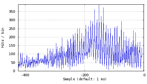
Most designs feature input monitors. The basic functionality is an edge counter monitoring each input channel individually - if read out e.g. once per second one can easily display the rate of input pulses. Besides that there is a high-resolution mode available: One input channel can be selected and the counter be sampled with a given period, down to 100 ns per sample. A buffer stores up to 1000 samples that can be read out subsequently for detailed rate analysis, for example to check micro-structures of the spill or to see if hits close to each other deteriorate the detector performance.
Most TRB3 designs contain the feature to forward signals from any input to the CTS to be used for triggering. That is, any input to a TDC design or the data from ADC-AddOn crossing a configurable threshold can be selected to be forwarded to the CTS. The signal is sent on-board the TRB3 or using RJ-45 cables between boards. For convenient use, a coincidence between two groups of signals can be generated as well.
Using this features gives various options to trigger on input signals - without the need to install a dedicated signal cable to the CTS.

Do you have any devices that needs to be remote controlled using a RS232 or serial link? And there is no computer nearby to provide this interface?
Both TRB3 and TRB3sc include a UART module that can be controlled via TrbNet. The output uses LVTTL signals, but an external board can be used to convert to a real RS232.


