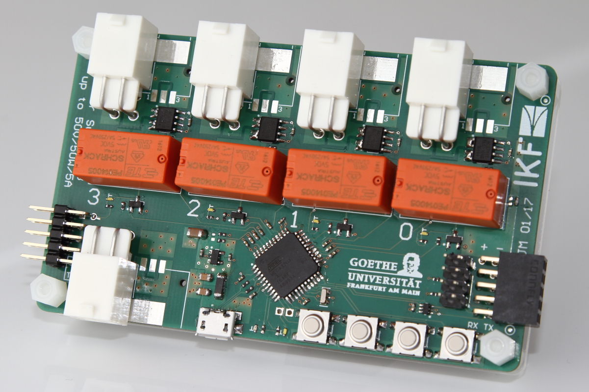
The new power switch module allows you to switch power to any other hardware remotely. The board can be equipped with both our standard power connectors and each channel is able to stand 50 V or 50 W or 5 A, whatever is reached first. Remote control is possible via USB or any available UART connection, for example via TrbNet and FPGA on a TRB3. The boards can be cascaded to "any" number of channels on a single control interface, as long as the power consumption of the board itself can be met. Features include current measurement on each output and programmable over current protection thresholds.
A
brief documentation exists.
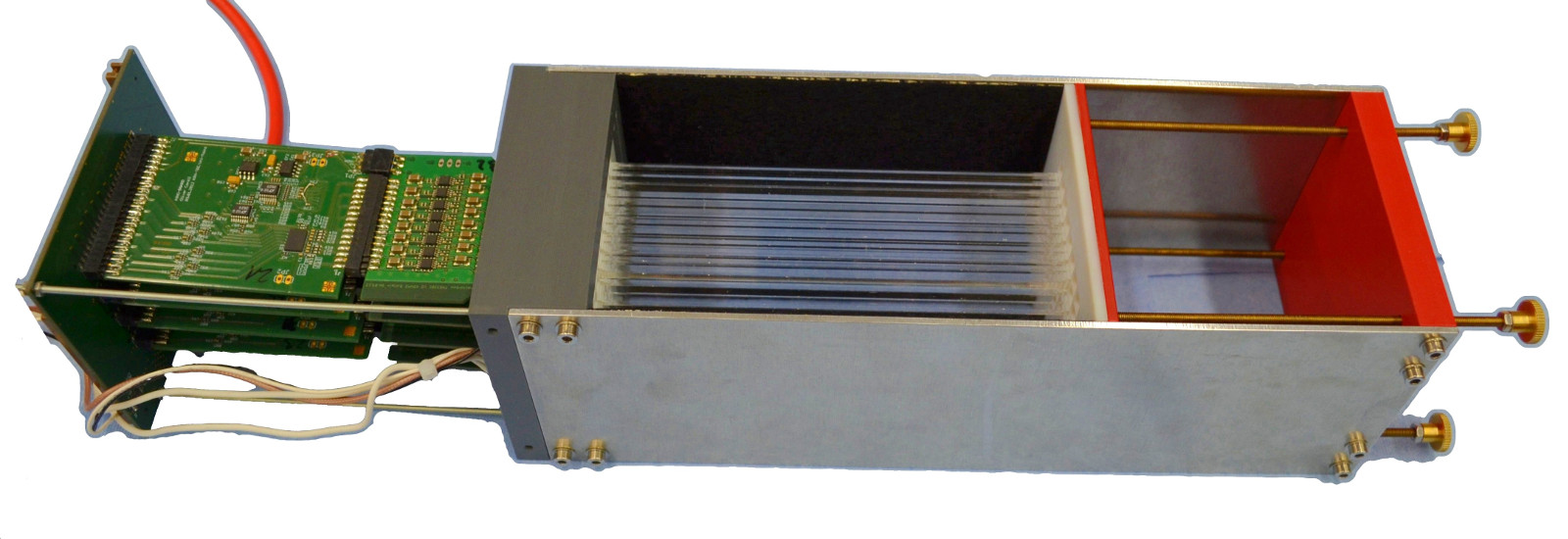
A segmented Fast Light Acquiring Start Hodoscope
(FLASH) prototype was constructed and tested at the Mainz Microtron
(MAMI). Its working principle is based on the detection of Cherenkov
light, produced inside radiator bars made of synthetic fused silica, by
fast Micro-Channel Plate PMTs (MCP-PMTs). The bars are inclined with
respect to the particle trajectory to match the Cherenkov angle to
mininmize reflections off the radiator surfaces.
The segmentation allows determining a coarse impact position (~few mm) and also repeatedly measuring the arrival time so
that an averaging procedure can be used to improve the timing precision.
The FLASH protoype is built around the PLANACON
64-channel MCP-PMT with a pore size of 10 micron. The radiator bars (5 x
5.5 x 140 mm^3) are arranged in an 8 x 8 matrix so that each radiator
bar matches a pixel on the MCP-PMT. The MCP-PMTs are equipped with
NINO-based frontend electronics providing leading edge time and
Time-over-Threshold (ToT). The frontend electronics is read out with
modified TRB boards where the DC/DC converters were taken off.
Two such units were tested using the 855 MeV
electron beam of MAMI. The detector response was investigated and the
basic characteristics were extracted. The timing performance was studied and
the ToT information was used to perform walk corrections. The best
timing precision achieved was ~50 ps per FLASH unit. The results are also published here:
http://dx.doi.org/10.1016/j.nima.2017.02.080
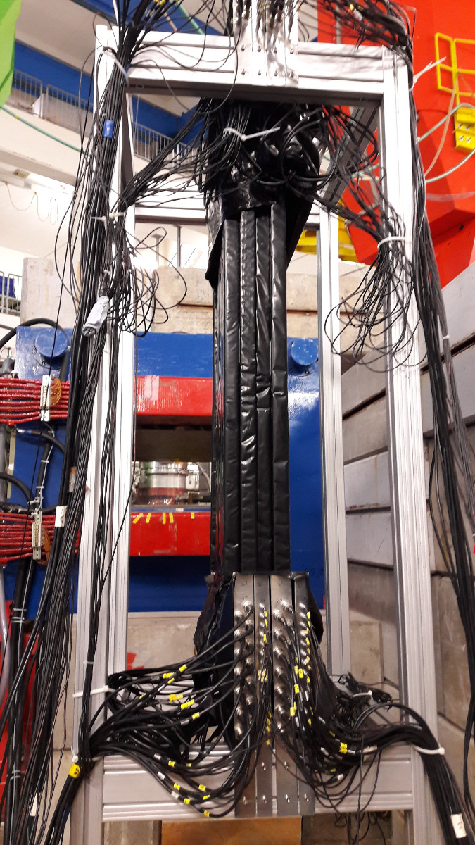
A prototype of the A1 Neutron Detector comprising 24 plastic scintillator bars and four plastic scintillator veto panels was tested in the Three-Spectrometer-Hall at the Mainz Microtron (MAMI). Each scintillator bar or veto strip is instrumented with two PMTs enabling position reconstruction along the bar axis via timing between the two PMTs. Furthermore, Time-over-Threshold (ToT) information is used to suppress background from charged particles. In addition, very high rates per scintillator (~MHz) are expected for the final experiment.
The PMT signals are send to NINO frontend boards which, in turn, are read out by a TRB system. Using the CBM-MBS external trigger module the A1 trigger number is also included in the data stream.
All of these requirements were successfully tested during the recent test beam time in Mainz.
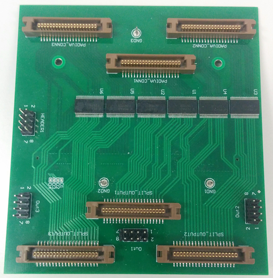
A new adapter AddOn is available, designed by the Krakow group: It features three inputs, identical to those on the 4conn-AddOn to connet Padiwa front-ends. All 48 LVDS input signals are fanned out to a second set of connectors to allow them to be forwarded to another read-out systsm or the CTS.
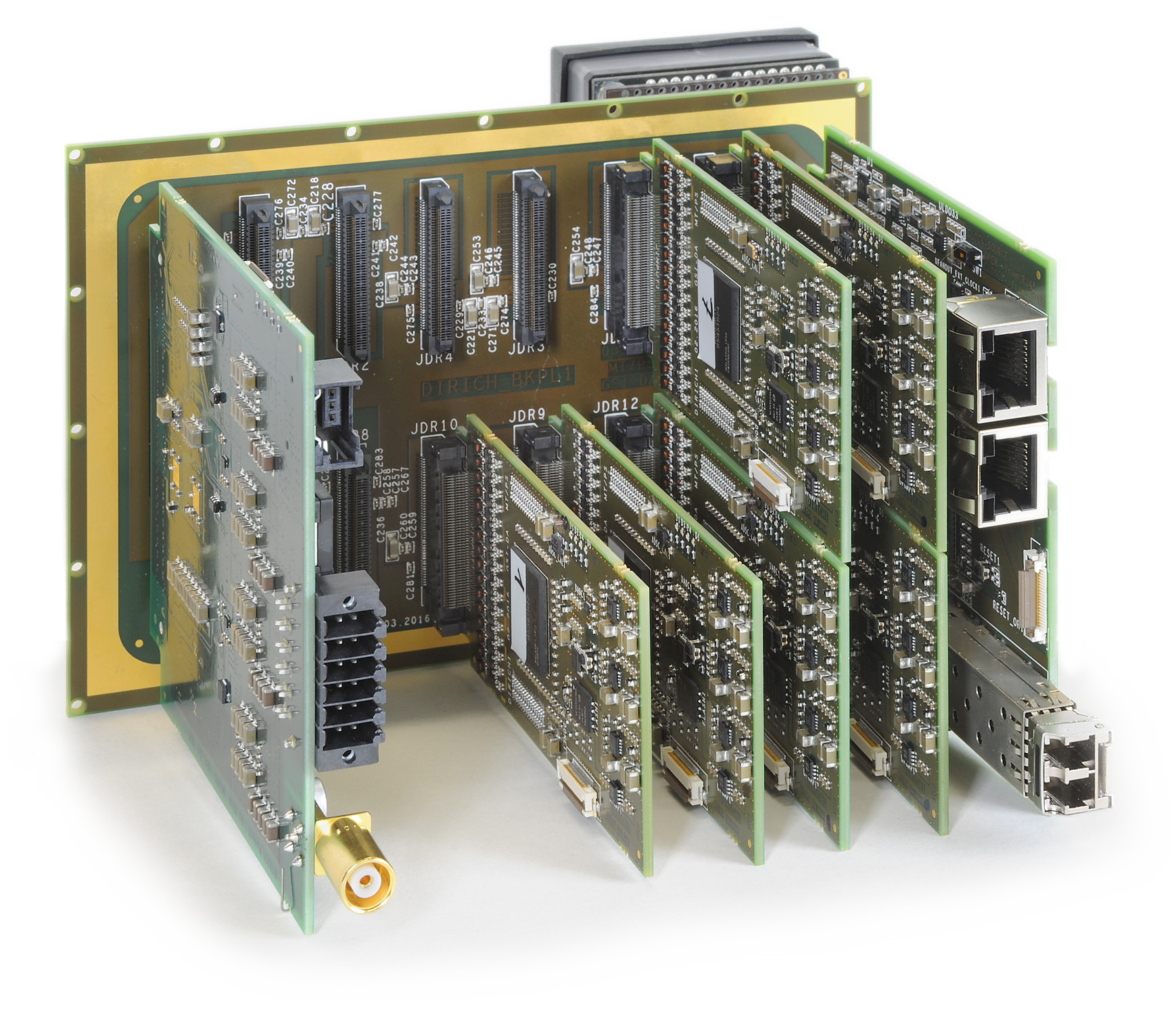
And here it is, the complete module for the Hades and CBM RICH detectors: 6 64-channel MC-PMTs and all electronics for read-out
- The backplane (10x15cm) holds all components. 14 layers in the PCB route all analog and digital signals as well as power
- The power module regulates all necessary supply voltages and provides the HV connection
- The concentrator module connects to the central DAQ and provides trigger and slow-control to all read-out modules
- The DiRich front-end module with in-FPGA TDC and the analog preamplifier stage, see two posts below
An extensive description of the features can be found on a
poster, presented at TWEPP 2016.
Photo: Gabi Otto, GSI


